Sanyo CH3682 Manuel d'utilisateur
Naviguer en ligne ou télécharger Manuel d'utilisateur pour Adoucisseurs Sanyo CH3682. Sanyo CH3682 User Manual Manuel d'utilisatio
- Page / 109
- Table des matières
- DEPANNAGE
- MARQUE LIVRES
Noté. / 5. Basé sur avis des utilisateurs
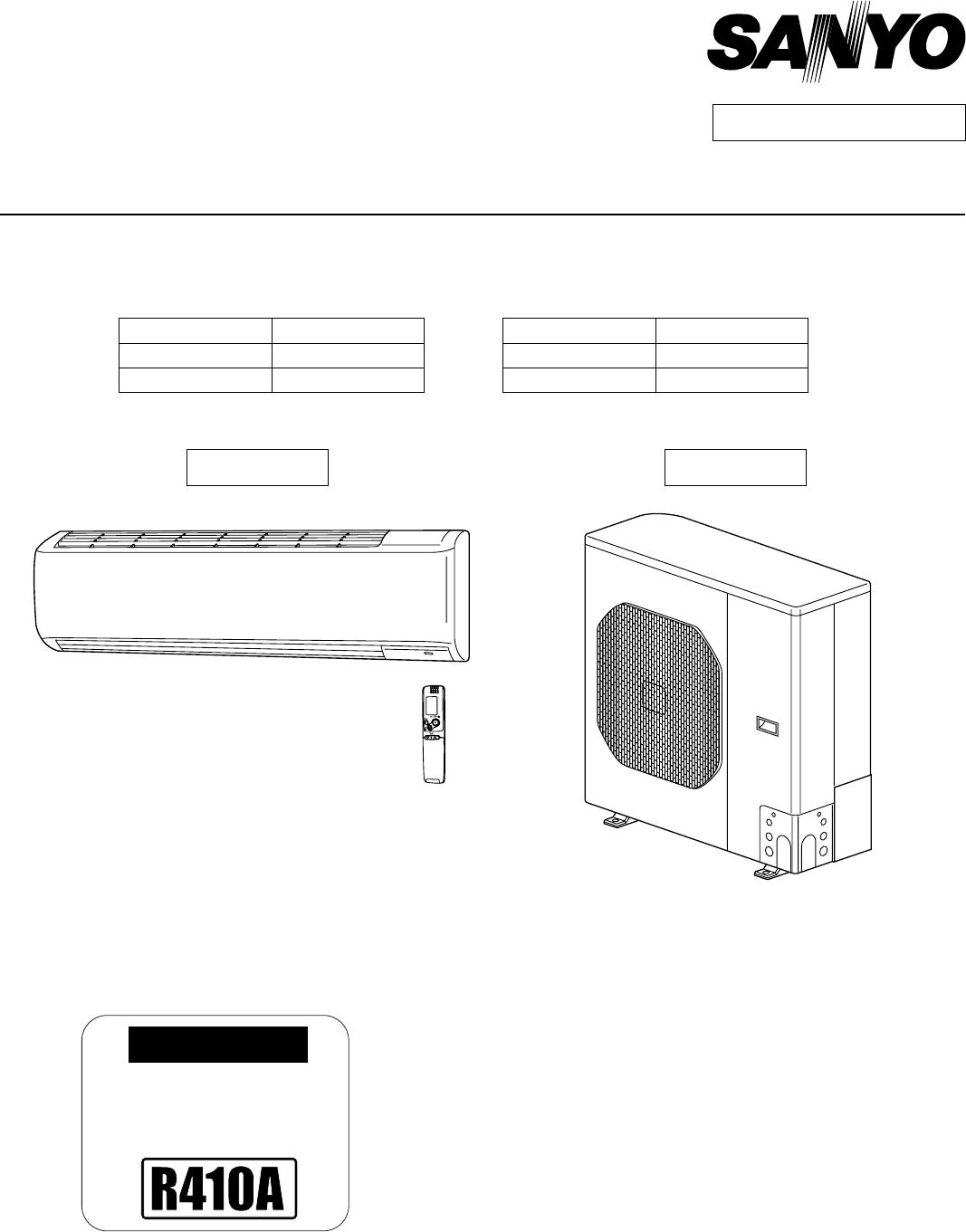
IMPORTANT
These air conditioners employ new
refrigerant R410A.
Pay special attention when
servicing the unit.
TECHNICAL & SERVICE MANUAL
KHS3082 + CH3082
KHS3682 + CH3682
DC INVERTER SPLIT SYSTEM AIR CONDITIONER
Destination: North America
Outdoor Model No.
CH3082
CH3682
Product Code No.
1 852 354 32
1 852 354 33
Indoor Unit Outdoor Unit
KHS3082
KHS3682
CH3082
CH3682
Indoor Model No.
KHS3082
KHS3682
Product Code No.
1 852 354 28
1 852 354 29
REFERENCE NO.
SM700858
FILE NO.
- KHS3082 + CH3082 1
- KHS3682 + CH3682 1
- SAFETY PRECAUTIONS 2
- Prohibit 3
- Table of Contents 4
- 1. OPERATING RANGE 6
- 2. SPECIFICATIONS 7
- Indoor Unit KHS3082 8
- Outdoor Unit CH3082 8
- < 230V > 9
- Indoor Unit KHS3682 10
- Outdoor Unit CH3682 10
- < 208V > 10
- 2-2-1. Indoor Unit 11
- 2-2-2. Outdoor Unit 13
- 3. DIMENSIONAL DATA 16
- Outdoor Unit CH3082 17
- CH3682 17
- 4. REFRIGERANT FLOW DIAGRAM 18
- 5. PERFORMANCE DATA 19
- Indoor air temp.73 20
- Hi FanLo fan 21
- 5-2. Cooling Capacity 23
- < Cooling Capacity > 24
- Indoor Unit : KHS3682 25
- Outdoor Unit : CH3682 25
- 5-3. Heating Capacity 27
- °F (21.1°C) 29
- Indoor Unit KHS3082 29
- Indoor Unit KHS3682 30
- 6. ELECTRICAL DATA 31
- Indoor Unit 32
- Outdoor Unit 32
- KHS3682 33
- 7. FUNCTIONS 35
- HIGH POWER 36
- NIGHT SETBACK 36
- Lamp colors 36
- Timer backup 36
- Dip switch (SW01) 37
- Power lamp 37
- Control P.C.Board 37
- Inspection panel 37
- Slide downward 37
- 7-2. Protective Functions 39
- Defrost detection and release 40
- 8. TROUBLESHOOTING 41
- (1) OPERATION lamp 42
- (2) TIMER lamp 42
- (3) LED CLEAN lamp 42
- INDOOR UNIT 42
- (1) Checking the indoor unit 44
- (2) Checking the outdoor unit 44
- (3) (2) (1) 45
- Defect in the outdoor unit 46
- P. C. board 46
- Defect or connection error 46
- 8-4-1. Indoor Fan Motor 48
- 8-4-2. Outdoor Fan Motor 49
- (1) Noise malfunction 50
- Resistance 51
- PCB Ass'y 52
- 10. REFRIGERANT R410A: 53
- INSTRUCTION MANUAL 60
- APPENDIX A 60
- This air conditioner uses 61
- FEATURES 62
- CONTENTS 62
- OI-149-3-EG 63
- NAMES OF PARTS 64
- UNIT DISPLAY AND OPERATION 64
- REMOTE CONTROL UNIT (DISPLAY) 65
- REMOTE CONTROL UNIT 66
- OI-149-7-EG 67
- USING THE REMOTE CONTROL UNIT 68
- 1. Automatic Operation 69
- 2. Manual Operation 69
- 3. Adjusting the Fan Speed 70
- 4. Fan Only 70
- 5. Night Setback Mode 70
- 6. QUIET Mode 70
- 7. HIGH POWER Mode 71
- 8. LED CLEAN Mode 71
- 9. UNOCCUPIED Mode 71
- SPECIAL REMARKS 72
- SETTING THE TIMER 73
- USING THE 1-HOUR OFF 74
- TIPS FOR ENERGY SAVING 74
- ADJUSTING THE AIRFLOW 75
- DIRECTION 75
- OPERATION WITHOUT THE 75
- CARE AND CLEANING 75
- OI-149-16-EG 76
- TROUBLESHOOTING 77
- OPERATING RANGE 77
- WIRED REMOTE CONTROLLER 77
- INSTALLATION INSTRUCTIONS 79
- SPECIAL PRECAUTIONS 80
- 1. General 81
- 6" (15 cm) 83
- Min. 8" (20 cm) 83
- About 1/2 of the unit height 84
- Unit: inch 85
- 3/16" 91
- (4.8 mm) dia. hole 91
- Rawl plug 91
- OUTDOOR 94
- Strip 15/16" (25 mm) 96
- Strip 3/8" (10 mm) 96
- Rear panel 97
- Drain hose 98
- Drain cap 98
- Inter-unit 100
- Power supply line 100
- (conduit) 100
- 5. Refrigerant Tubing 101
- Insulated tubes 102
- Apply putty here 102
- 6. Air Purging 103
- Pump Down 106
- Service Valve Connections 107
- 8. Address Switch 108
Résumé du contenu
Page 1 - KHS3682 + CH3682
IMPORTANTThese air conditioners employ newrefrigerant R410A.Pay special attention whenservicing the unit.TECHNICAL & SERVICE MANUALKHS3082 + CH308
Page 2 - SAFETY PRECAUTIONS
Indoor Unit KHS3682Outdoor Unit CH3682< 208V > DATA SUBJECT TO CHANGE WITHOUT NOTICE.Remarks: Rating conditions are:Cooling: Indoor air temperat
Page 3 - Prohibit
224. How to Install the Outdoor UnitFirst refer to Section 2. Installation Site Selection.4-1. Wiring Instructions for the Outdoor UnitRegulations on
Page 4 - Table of Contents
235. Refrigerant Tubing5-1. Use of the Flaring MethodMany of the conventional split system air conditionersemploy the flaring method to connect refrig
Page 5
245-4. Connecting Tubing between Indoor and Outdoor Unitsa) Tightly connect the indoor side refrigerant tubing exten-ded from the wall with the outdoo
Page 6 - 1. OPERATING RANGE
256. Air PurgingAir and moisture remaining in the refrigerant systemhave undesirable effects as indicated below. Therefore,they must be purged complet
Page 7 - 2. SPECIFICATIONS
26(5) With the vacuum pump still running, close the “Lo”knob of the manifold valve. Then stop the vacuumpump.(6) With the hex wrench, turn the valve s
Page 8 - Outdoor Unit CH3082
27How to Test Run the Air ConditionerAfter turning on the power of the air conditioner, use theremote controller and follow the steps below to conduct
Page 9 - < 230V >
28 Pump DownPump down means collecting all refrigerant gas in thesystem back into the outdoor unit without losing any ofthe gas. Pump down is used wh
Page 10 - < 208V >
a) Temporary connection:Screw in 3 – 5 turns by hand. (Fig. 60c)b) To fasten the flare nuts, apply specified torqueas Table 9 and Fig. 60d.Fig. 60c Fi
Page 11 - 2-2-1. Indoor Unit
308. Address Switch8-1. Address Setting of the Remote Control UnitThe address can be set in order to prevent interferencebetween remote controllers wh
Page 12
For Parts or Service Assistance please contact your local Sanyo HVAC Contractor or DistributorUnited States: SCS, HVAC SolutionsWeb: www.SanyoHVAC.com
Page 13 - 2-2-2. Outdoor Unit
Indoor Unit KHS308224BYJ48-1256Flap MotorType Stepping MotorRating ModelCoil Resistance Ohm(Ambient Temp. 77 °F (25 °C))Each Pair of Terminal : 200 +/
Page 14
Indoor Unit KHS3682Flap MotorTypeRating ModelCoil Resistance Ohm(Ambient Temp. 77 °F (25 °C)) Face Area CoilRowsFins Per inchHeat Exchanger Coilft2 (m
Page 15
Outdoor Unit CH30822-2-2. Outdoor UnitP.C.BoardCircuit Fuse ControlsPart No.-250V 25APOW-CH3082-B1Noise Filer P.C.BMicroprocessor400V 3.5ACR-CH3082-F
Page 16 - 3. DIMENSIONAL DATA
Outdoor Unit CH3682P.C.BoardCircuit Fuse ControlsPart No.-250V 25APOW-CH3082-B1Noise Filer P.C.BMicroprocessor400V 3.5ACR-CH3682-FControl P.C.B--HIC-C
Page 17 - CH3682
2-3. Other Component Specifications Indoor Unit KHS3082 KHS3682Outdoor Unit CH3082 CH3682032 50 68 86 104 122 140 158 176 194(0) (10) (20) (30) (
Page 18 - 4. REFRIGERANT FLOW DIAGRAM
3. DIMENSIONAL DATAIndoor Unit KHS3082 KHS3682Unit: inch(mm)(852-0-0010-19600-0)41-15/16 (1065)9-1/16 (230) (3/32)7-25/32Wide tube dia. 5/8"
Page 19 - 5. PERFORMANCE DATA
Outdoor Unit CH3082 CH3682Unit: inch(mm)(852-0-0010-19400-1)6-11/6 25-31/32 4-11/322-15/162-3/82-ID:1-1/4 holes (holes for drain)Of the 4-ID:1-1/4
Page 20 - Indoor air temp.73
Compressor4-wayvalveMainAccumulatorHigh pressureswitchWide tubeservicevalveWide tubeSubAccumulatorNarrowtubeservicevalveNarrow tubeHeat exchangerHeat
Page 21 - Hi FanLo fan
5. PERFORMANCE DATA5-1. Temperature ChartsIndoor Unit KHS3082Outdoor Unit CH3082• Check each performance value in test-run mode. Electrical perfor
Page 22
• Before doing repair work, please read the " SAFETY PRECAUTIONS" carefully and fully understand them. • The precautionary items here
Page 23 - 5-2. Cooling Capacity
Indoor Unit KHS3082Outdoor Unit CH3082• Check each performance value in test-run mode. Electrical performance values represent a combined indoor/o
Page 24 - < Cooling Capacity >
Indoor Unit KHS3682Outdoor Unit CH3682Cooling Characteristics (RH : 46%, Indoor fan speed : High fan) (60Hz, 230V)(1) Low pressure performance cha
Page 25 - Outdoor Unit : CH3682
Indoor Unit KHS3682Outdoor Unit CH3682Indoor discharge air temperature °F(°C)23(–5)32(0)41(5)50(10)59(15)68(20)77(25)Outdoor inlet air D.B. temp.
Page 26
Indoor Unit : KHS3082Outdoor Unit : CH3082Power Supply : 230V Single Phase 60Hz< Cooling Capacity (Low Ambient) >5-2. Cooling CapacityTC
Page 27 - 5-3. Heating Capacity
1.Rating conditions (#) : Indoor Unit Entering Air Temp. 80 °F (26.7 °C) D.B. / 67 °F (19.4 °C) W.B.: Outdoor Ambient Temp. 95 °F (35 °C) D.B.2.3. A
Page 28
Indoor Unit : KHS3682Outdoor Unit : CH3682Power Supply : 230V Single Phase 60Hz< Cooling Capacity (Low Ambient) >TC : Total Cooling Capaci
Page 29 - Indoor Unit KHS3082
Indoor Unit : KHS3682Outdoor Unit : CH3682Power Supply : 230V Single Phase 60Hz< Cooling Capacity >TC : Total Cooling Capacity (BTU/h) S
Page 30 - Indoor Unit KHS3682
Indoor Unit : KHS3082Outdoor Unit : CH3082Power Supply : 230V Single Phase 60Hz< Heating Capacity >5-3. Heating CapacityTH : Total Heatin
Page 31 - 6. ELECTRICAL DATA
Indoor Unit : KHS3682Outdoor Unit : CH3682Power Supply : 230V Single Phase 60Hz< Heating Capacity >TH : Total Heating Capacity (BTU/h)1.Ra
Page 32 - Outdoor Unit
Horizontal distance (ft.)Axis air velocity (ft./sec.)Vertical distance (ft.)Room air temp. :70°F (21.1°C)Fan speed : HighHeatingHorizontal distance (f
Page 33 - KHS3682
WarningIf refrigerant gas blows off during the work, do not touch the refrigerant gas as it may cause frostbite.If refrigerant gas leaks during the wo
Page 34
Horizontal distance (ft.)Axis air velocity (ft./sec.)Vertical distance (ft.)Room air temp. :70°F (21.1°C)Fan speed : HighHeatingHorizontal distance (f
Page 35 - 7. FUNCTIONS
6. ELECTRICAL DATA6-1. Electrical CharacteristicsIndoor UnitKHS3082Outdoor UnitCH3082Indoor Unit Outdoor UnitFan Motor Fan Motor + CompressorPerfo
Page 36 - Timer backup
Indoor UnitKHS3682Outdoor UnitCH3682Indoor Unit Outdoor UnitFan Motor Fan Motor + CompressorPerformance at 230V Single-phase 60HzRating conditions
Page 37 - Slide downward
8FA2-5250-70400-36-2. Electric Wiring DiagramsIndoor Unit KHS3082 KHS3682EVAPORATORTERMINAL BASETO OUTDOOR UNITLAMP9P(WHT)FLAP5P (WHT)MFLAP MOTORRE
Page 38
Outdoor Unit CH3082 CH36828FA2-5250-70000-112345INDOORUNITPOWER SUPPLYGNDTERMINAL (5P)CRANKCASEHEATERFAN MOTOR MAGNETIC COILCOIL THERMISTORNOISE
Page 39 - 7-2. Protective Functions
Emergency operation SENSOR DRYAUTO cooling/heating operation Selecting the operation mode During DRY operation, the system adjusts the room temperat
Page 40 - Defrost detection and release
HIGH POWERNIGHT SETBACKLamp colorsTimer backupThis function acts to raise the power but keeps the AC system in the same operating mode.This function i
Page 41 - 8. TROUBLESHOOTING
The noise reducing control is the function used for silent operation of the air conditioner by means of setting the dip switch on the outdoor unit P.C
Page 42 - INDOOR UNIT
The maximum current value is changed to 14A (for CH3082) or 17A (for CH3682) to prevent power breaker tripping. (It is set to 24A (in cooling) or 22A
Page 43
Overload prevention during heatingDuring HEAT operation, the temperature of the indoor heat exchanger is used to control the frequency and lessen the
Page 44 - (2) Checking the outdoor unit
Table of Contents SAFETY PRECAUTIONSTABLE OF CONTENTS1. OPERATING RANGE2. SPECIFICATIONS2-1. Unit Specifications 2-2. Major Component Specifi
Page 45 - (3) (2) (1)
This function prevents the circuit breaker or fuse from operating to open the circuit. This function works when electrical current has increased due t
Page 46 - Defect or connection error
8. TROUBLESHOOTING8-1. Precautions before Performing Inspection or RepairNOTEAfter checking the self-diagnostics monitor, turn the power OFF before
Page 47
Since the indications cover various units, the corresponding parts listed below may not be present in some models.(1) OPERATION lamp(2) TIMER lamp(
Page 48 - 8-4-1. Indoor Fan Motor
(2) If the self-diagnostics function fails to operateCheck the indoor unit.Is the fuse blown?Replace the controller.Replace the circuitboard or the fu
Page 49 - 8-4-2. Outdoor Fan Motor
8-3. Checking the Indoor and Outdoor Units(1) Checking the indoor unit(2) Checking the outdoor unit Using the TEST/T-RUN terminalsControlNo. Check ite
Page 50 - (1) Noise malfunction
(3) Serial Communication Error Identification ProcedureRefer to "Method of Self-Diagnostics" for the self-diagnostics procedure.(3-1) Alarm
Page 51 - Resistance
What is the latest self-diagnosis result ?Alarm Code : E07/P04/P05/P20/P27Alarm Code : E07/P04/P05/P20/P27Defect in the outdoor unitP. C. board.Alarm
Page 52 - PCB Ass'y
(3-2) Alarm Code : E07/P04/P05/P20/P27Troubleshooting Serial Communication1. Turn off the power and wait until the power lamp (LED) of the outdoor u
Page 53 - 10. REFRIGERANT R410A:
[Trouble symptom 3] Motor rotates for some time (several seconds), but then quickly stops, when the indoor unit operates.(There is trouble in the sys
Page 54
8-4-2. Outdoor Fan MotorThis outdoor DC fan motor contains an internal control PCB. Therefore, it is not possible to measure the coil resistance, and
Page 55
9. CHECKING ELECTRICAL COMPONENTS9-1. Measurement of Insulation Resistance9-2. Checking Continuity of Fuse on PCB Ass'y10. REFRIGERANT R410A:
Page 56
8-5. Noise Malfunction and Electromagnetic InterferenceAn inverter A/C operates using pulse signal control and high frequencies. Therefore, it is sus
Page 57
Insulation testerProbeClipGround wireTerminal plateCoppertube ormetallic partClipInsulation testerProbeFig. 1Fig. 2Fig. 3Fig. 4Coppertube ormetallic p
Page 58
FusePCB Ass'yFig. 5Fig. 6Fuse9-2. Checking Continuity of Fuse on PCB Ass'yRemove the PCB Ass'y from the electrical component box. Then
Page 59
10. REFRIGERANT R410A: SPECIAL PRECAUTIONS WHEN SERVICING UNIT10-1. Characteristics of New Refrigerant R410A10-1-1. What is New Refrigerant R410A?R
Page 60 - APPENDIX A
Tubing precautionsRefrigerant R410A is more easily affected by dust or moisture compared with R22, thus be sure to temporarily cover the ends of the t
Page 61 - This air conditioner uses
10-3. Tools Specifically for R410A For servicing, use the following tools for R410AGauge manifoldCharging hoseGas leak detectorRefrigerant cylinderCh
Page 62 - CONTENTS
10-5. In Case of Compressor Malfunction CAUTIONShould the compressor malfunction, be sure to make the switch to a replacement compressor as quickly a
Page 63 - OI-149-3-EG
ValveSingle valveCharge liquid refrigerant with cylinder in up-side-down position.Single valve (with siphon tube)Charge with cylinder in normal positi
Page 64 - UNIT DISPLAY AND OPERATION
Length of tubingEvacuation timeLess than 33 ft. (10 m)More than 10 minutesMore than 33 ft. (10 m)More than 15 minutes10-6. In Case Refrigerant is Le
Page 65 - REMOTE CONTROL UNIT (DISPLAY)
10-7. Charging Additional Refrigerant10-7-1. When Tubes are ExtendedObserve the proper amount of refrigerant as stated in this service manual or the
Page 66 - REMOTE CONTROL UNIT
95 °F D.B. / 71 °F W.B.67 °F D.B. / 57 °F W.B.80 °F D.B. / 67 °F W.B. _ D.B. / _ W.B.1. OPERATING RANGEMaximumMinimumMaximumMinimum115 °F D.B.0 °
Page 67 - OI-149-7-EG
INSTRUCTION MANUALKHS3082 + CH3082KHS3682 + CH3682(OI-852-6-4181-149-00-0)APPENDIX AA-1
Page 68 - USING THE REMOTE CONTROL UNIT
KHS3082KHS3682COOL/DRY/HEAT Model© SANYO 2010Pub. OI-85264181149000INSTRUCTION MANUALInverter-Controlled Split System Air ConditionerMODE D’EMPLOIClim
Page 69 - 2. Manual Operation
2FEATURESThis air conditioner is an inverter type unit that automatically adjusts capability as appropriate. Details on these functions are provided b
Page 70 - 6. QUIET Mode
3PRODUCT INFORMATIONIf you have problems or questions concerning your Air Conditioner, you will need the following information. Model and serial numbe
Page 71 - 9. UNOCCUPIED Mode
4NAMES OF PARTSThis illustration is based on the external view of a standard model.Consequently, the shape may differ from that of the air conditioner
Page 72 - SPECIAL REMARKS
5REMOTE CONTROL UNIT (DISPLAY)(1) Operation modeAUTO ...HEAT...MILD DRY ...
Page 73 - SETTING THE TIMER
6REMOTE CONTROL UNITTransmitterWhen you press the buttons on the remote control unit, the mark appears in the display to transmit the setting change
Page 74 - TIPS FOR ENERGY SAVING
7SensorA temperature sensor inside the remote control unit senses the room temperature.(Cover closed)CLOCK buttonACL button (ALL CLEAR)Puts the remote
Page 75 - CARE AND CLEANING
8USING THE REMOTE CONTROL UNITHOW TO INSTALL BATTERIES1. Slide the cover in the direction indicated by the arrow and remove it.2. Install two AAA alka
Page 76 - OI-149-16-EG
9OPERATION WITH THE REMOTE CONTROL UNIT1. Automatic OperationThis unit automatically switches between cooling operation and heating operation accordin
Page 77 - WIRED REMOTE CONTROLLER
2. SPECIFICATIONS2-1. Unit SpecificationsIndoor Unit KHS3082Outdoor Unit CH3082< 230V >DATA SUBJECT TO CHANGE WITHOUT NOTICE.Remarks: Rating c
Page 78
103. Adjusting the Fan SpeedA. Automatic fan speedSimply set the FAN SPEED selector button to the position.This automatically sets the best fan spe
Page 79 - INSTALLATION INSTRUCTIONS
117. HIGH POWER ModeHIGH POWER mode can be used to increase the output of the indoor unit for all operation modes except automatic operation.Press th
Page 80 - SPECIAL PRECAUTIONS
12A. In Heating Mode: ( )B. In Cooling Mode: ( )• Unoccupied Mode triggers Heating or Cooling Operation in response to the room temperature, but when
Page 81 - 1. General
13SETTING THE TIMERIn the descriptions below, the following settings are used for the temperature and time indicator selector button on the bottom fro
Page 82
144. How to set daily ON/OFF repeat timer(Example) To start operation at 7:10 am. and stop the air conditioner at 11:00 am. • The ON/OFF combination t
Page 83 - Min. 8" (20 cm)
15ADJUSTING THE AIRFLOW DIRECTION1. HorizontalThe horizontal airflow can be adjusted by moving the vertical vanes with your hands to the left or right
Page 84 - About 1/2 of the unit height
16If these parts are stained, use a clean cloth moistened with a mild liquid detergent. When cleaning the grille, be careful not to force the vanes ou
Page 85 - Unit: inch
17RemountingGrasp the sections near the front panel arms on both sides, and hold the front panel so that it is nearly horizontal. Push the arm shafts
Page 86
INSTALLATION INSTRUCTIONSAPPENDIX BKHS3082 + CH3082KHS3682 + CH3682(II-852-6-4190-498-00-0)A-2
Page 87
ContentsPageIMPORTANT!Please Read Before Starting ... 21. GENERAL ...
Page 88
Indoor Unit KHS3082Outdoor Unit CH3082< 208V >DATA SUBJECT TO CHANGE WITHOUT NOTICE.Remarks: Rating conditions are:Cooling: Indoor air temperatu
Page 89
2IMPORTANT! Please Read Before StartingThis air conditioning system meets strict safety and operatingstandards. As the installer or service person, it
Page 90
31. GeneralThis booklet briefly outlines where and how to install theair conditioning system. Please read over the entire setof instructions for the i
Page 91 - Rawl plug
41-5. Additional Materials Required for Installation1. Refrigeration (armored) tape2. Insulated staples or clamps for connecting wire(See local codes.
Page 92
● Concerning air-intake side distance “A” (Fig. 5a)The minimum for distance “A” is 6" if there are noobstructions on the air-discharge side (wall
Page 93
6Fig. 5eFig. 5fFig. 5g2-2-1. Installing the Unit in an Area with High Winds and in a Snowy Area● In locations with high winds, a wind-proof duct sho
Page 94 - OUTDOOR
711-13/16" 13-3/8"25-3/16"22-7/8"(6-21/32")6-5/16"21-25/32" (12-9/16")2-11/16"35-13/16"37-1/32"
Page 95
8Required space around the outdoor unitIf the wind-proof duct is used, the space shown below must be secured around the outdoor unit.If the unit is us
Page 96 - Strip 3/8" (10 mm)
925-13/32"3/32"13-3/8"(11-15/16")16-15/16"Air IntakeAir discharge39-1/4"27-7/32"7-1/32"35-15/16"28-15/16&
Page 97 - Rear panel
10Reference diagram for snow-proof ductSpace requirements for settingCH3082/3682 with STK-BDV80EMin. 39-3/8" or more(1) Single-unit installation(
Page 98 - Drain cap
11Min. 39-3/8"or moreMin. 11-13/16"or moreMin. 11-13/16"or moreMin. 19-11/16"or moreMin. 59-1/16"or moreMin. 78-3/4"or m
Page 99
Indoor Unit KHS3682Outdoor Unit CH3682< 230V >DATA SUBJECT TO CHANGE WITHOUT NOTICE.Remarks: Rating conditions are:Cooling: Indoor air temperatu
Page 100 - (conduit)
Rear panelFig. 7cRear panelFig. 7b12Set screw only for transportationFig. 6Rear panelmarksFig. 7aLefttubingRighttubingRight-reartubing(recommended)Rig
Page 101 - 5. Refrigerant Tubing
13IndoorsideOutdoorsideHole should be made at a slight downward slant to theoutdoor side.NOTEFig. 10Plastic coverINSIDE OUTSIDEWallSlightanglePVC pipe
Page 102 - Apply putty here
3-4. Removing and Installing the GrilleBasically, these models can be installed and wired with-out removing the grille. If access to any internal part
Page 103 - 6. Air Purging
153-5. Shape the Indoor Side Tubing(1) Arrangement of tubing by directiona) Right or left tubingCut out the corner of the right/left frame with ahacks
Page 104
163-7. Wire Size and LengthRegulations on wiring diameter differ from locality to locality. For field wiring requirements, please refer to your local
Page 105
173-8. Wiring Instructions for Inter-unit Connections(1) Insert the inter-unit wiring (according to local codes)into the through-the-wall PVC pipe. Ru
Page 106 - Pump Down
18When connecting each power wire to the correspondingterminal, follow the instructions “How to connect wiringto the terminal” and fasten the wire sec
Page 107 - Service Valve Connections
193-9. Mounting(1) To install the indoor unit, mount the indoor unit ontothe 3 tabs on the upper part of the rear plate.(2) Hold down the air discharg
Page 108 - 8. Address Switch
20Hole in wallBent partNarrow tubeWide tubeRear panelFig. 38Drain cap Drain hoseClampFig. 39 Left-side tubing(1) Lead the tubing and drain hose throu
Page 109
21To unmount indoor unitPress the 2 ▲ marks on the lower part of the indoor unitand unlatch the tabs. Then lift the indoor unit andunmount. (Fig. 42)3
Produits connexes et manuels pour Adoucisseurs Sanyo CH3682
 (36 pages)
Adoucisseurs Sanyo AHX0752 Manuel d'utilisateur
 (114 pages)
(114 pages)
Adoucisseurs Sanyo C3682 Manuel d'utilisateur
(104 pages)
(104 pages)
© 2020, manymanuals.fr. Tous droits réservés | 1.642 s |
 Manymanuals.com
 Manymanuals.de
 Manymanuals.fr
 Manymanuals.it
 Manymanuals.pl
 Manymanuals.cz
 Manymanuals.es
 Manymanuals-pt.com
Commentaires sur ces manuels